|


 |  |

| Aeronautica | Comunicatii | Drept | Informatica | Nutritie | Sociologie |
| Tehnica mecanica |
Tehnica mecanica
|
|
Qdidactic » stiinta & tehnica » tehnica mecanica Electromechanical Devices - basic Induction Motor Concepts |
Electromechanical Devices - basic Induction Motor Concepts
CHAPTER 7 - INDUCTION MOTOR
Summary:
Induction Motor Construction
Basic Induction Motor Concepts
The Development of Induced Torque in an Induction Motor.
The Concept of Rotor Slip.
The Electrical Frequency on the Rotor.
The Equivalent Circuit of an Induction Motor.
The Transformer Model of an induction Motor.
The Rotor Circuit Model.
The Final Equivalent Circuit.
Powers and Torque in Induction Motor.
Losses and Power-Flow diagram
Power and Torque in an Induction Motor.
Separating the Rotor Copper Losses and the Power Converted in an Induction Motor's Equivalent Circuit.
Induction Motor Torque-Speed Characteristics
Induced Torque from a Physical Standpoint.
The Derivation of the Induction Motor Induced-Torque Equation.
Comments on the Induction Motor Torque Speed Curve.
Maximum (Pullout) Torque in an Induction Motor.
Variations in Induction Motor Toque-Speed Characteristics
Control of Motor Characteristics by Cage Rotor Design.
Deep-Bar and Double-Cage rotor design.
Induction Motor Design Classes.
Starting Induction Motors
Speed Control of Induction Motor
Induction Motor Speed Control by Pole Changing.
Speed Control by Changing the Line Frequency.
Speed Control by Changing the Line Voltage.
Speed Control by Changing the Rotor Resistance.
Determining Circuit Model Parameters
The No-Load Test
The DC Test
The Locked-Rotor Test
 Induction
machine - the rotor voltage that produces the rotor current and the rotor
magnetic field is induced in the rotor windings rather than being physically
connected by wires. No dc field current
is required to run the machine.
Induction
machine - the rotor voltage that produces the rotor current and the rotor
magnetic field is induced in the rotor windings rather than being physically
connected by wires. No dc field current
is required to run the machine.
Induction Motor Construction
There are basically 2 types of rotor construction:
a) Squirrel Cage no windings and no slip rings
b) Wound rotor - It has 3 phase windings, usually Y connected, and the winding ends are connected via slip rings.
Wound rotor are known to be more expensive due to its maintenance cost to upkeep the slip rings, carbon brushes and also rotor windings.
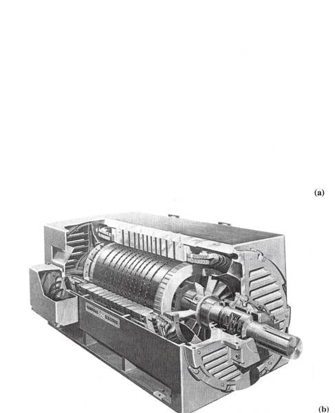
Cutaway
diagram of a typical large cage rotor induction motor
![]()
![]()
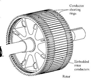
Sketch of cage
rotor
Typical wound
rotor for induction motors.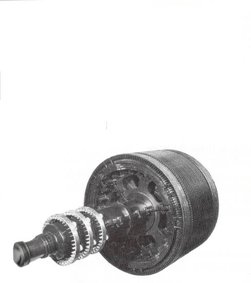
![]()
![]()
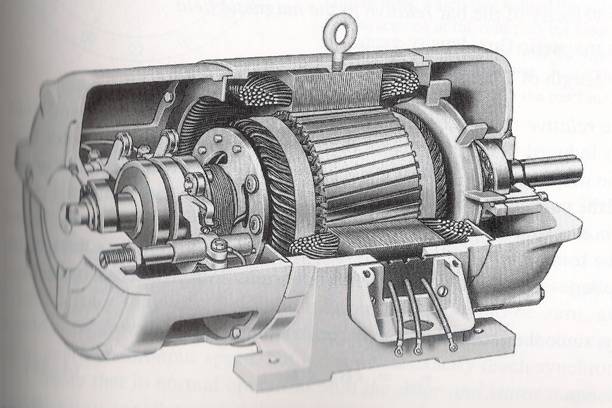
Cutaway
diagram of a wound rotor induction motor.
Basic Induction Motor Concepts
The Development of Induced Torque in an Induction Motor
When current flows in the stator, it will produce a magnetic field in stator as such that Bs (stator magnetic field) will rotate at a speed:
Where fe is the system frequency in hertz and P is the number of poles in the machine. This rotating magnetic field Bs passes over the rotor bars and induces a voltage in them. The voltage induced in the rotor is given by:
eind = (v x B) l
Hence there will be rotor current flow which would be lagging due
to the fact that the rotor has an inductive element. And this rotor current
will produce a magnetic field at the rotor,
![]()
The torque induced would generate acceleration to the rotor, hence the rotor will spin.
However, there is a finite upper limit to the motor's speed.
Conclusion : An induction motor can thus speed up to near synchronous speed but it can never reach synchronous speed.
The Concept of Rotor Slip
The induced voltage at the rotor bar is dependent upon the relative speed between the stator magnetic field and the rotor. This can be easily termed as slip speed:
![]()
Where nslip = slip speed of the machine
nsync = speed of the magnetic field.
nm = mechanical shaft speed of the motor.
Apart from that we can describe this relative motion by using the concept of slip:

Slip may also be described in terms of angular velocity, .

Using the ratio of slip, we may also determine the rotor speed:
![]()
The Electrical Frequency on the Rotor
An induction motor is similar to a rotating transformer where the primary is similar to the stator and the secondary would be a rotor. But unlike a transformer, the secondary frequency may not be the same as in the primary.
If the rotor is locked (cannot move), the rotor would have the same frequency as the stator (refer to transformer concept). Another way to look at it is to see that when the rotor is locked, rotor speed drops to zero, hence by default, slip is 1. But as the rotor starts to rotate, the rotor frequency would reduce, and when the rotor turns at synchronous speed, the frequency on the rotor will be zero.
Why?
Since

And rotor frequency may be expressed as:
![]()
Hence combing both equations would give:
And since nsync=120fe / P,

Which shows that the relative difference between synchronous speed and the rotor speed will determine the rotor frequency
Example 7.1
A 208V, 10hp, 4 pole, 60Hz, Y-connected induction motor has a full-load slip of 5%.
(a) What is the synchronous speed of this motor?
(b) What is the rotor speed of this motor at the rated load?
(c) What is the rotor frequency of this motor at the rated load?
(d) What is the shaft torque of this motor at the rated load?
The Equivalent Circuit of an Induction Motor
An induction motor relies for its operation on the induction of voltages and currents in its rotor circuit from the stator circuit (transformer action). This induction is essentially a transformer operation, hence the equivalent circuit of an induction motor is similar to the equivalent circuit of a transformer.
The Transformer Model of an Induction Motor
A transformer per-phase equivalent circuit, representing the operation of an induction motor is shown below:
The transformer model or an induction motor, with
rotor and stator connected by an ideal transformer of turns ratio aeff.

As in any transformer, there is certain resistance and self-inductance in the primary (stator) windings, which must be represented in the equivalent circuit of the machine. They are - R1 - stator resistance and
X1 - stator leakage reactance
Also, like any transformer with an iron core, the flux in the machine is related to the integral of the applied voltage E1. The curve of mmf vs flux (magnetization curve) for this machine is compared to a similar curve for a transformer, as shown below:
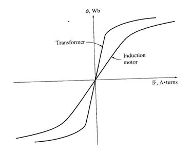
The slope of the induction motor's mmf-flux curve is much shallower than the curve of a good transformer. This is because there must be an air gap in an induction motor, which greatly increases the reluctance of the flux path and thus reduces the coupling between primary and secondary windings. The higher reluctance caused by the air gap means that a higher magnetizing current is required to obtain a given flux level. Therefore, the magnetizing reactance Xm in the equivalent circuit will have a much smaller value than it would in a transformer.
The primary internal stator voltage is E1 is coupled to the secondary ER by an ideal transformer with an effective turns ratio aeff. The turns ratio for a wound rotor is basically the ratio of the conductors per phase on the stator to the conductors per phase on the rotor. It is rather difficult to see aeff clearly in the cage rotor because there are no distinct windings on the cage rotor.
ER in the rotor produces current flow in the shorted rotor (or secondary) circuit of the machine.
The primary impedances and the magnetization current of the induction motor are very similar to the corresponding components in a transformer equivalent circuit.
The Rotor Circuit Model
When the voltage is applied to the stator windings, a voltage is induced in the rotor windings. In general, the greater the relative motion between the rotor and the stator magnetic fields, the greater the resulting rotor voltage and rotor frequency. The largest relative motion occurs when the rotor is stationary, called the locked-rotor or blocked-rotor condition, so the largest voltage and rotor frequency are induced in the rotor at that condition. The smallest voltage and frequency occur when the rotor moves at the same speed as the stator magnetic field, resulting in no relative motion.
The magnitude and frequency of the voltage induced in the rotor at any speed between these extremes is directly proportional to the slip of the rotor. Therefore, if the magnitude of the induced rotor voltage at locked-rotor conditions is called ER0, the magnitude of the induced voltage at any slip will be given by:
ER = sER0
And the frequency of the induced voltage at any slip is:
fr = sfe
This voltage is induced in a rotor containing both resistance and reactance. The rotor resistance RR is a constant, independent of slip, while the rotor reactance is affected in a more complicated way by slip.
The reactance of an induction motor rotor depends on the inductance of the rotor and the frequency of the voltage and current in the rotor. With a rotor inductance of LR, the rotor reactance is:
where XR0 is the blocked rotor reactance. The resulting rotor equivalent circuit is as shown:
The rotor circuit model of an induction motor.
The rotor current flow is:
Therefore, the overall rotor impedance talking into account rotor slip would be:
![]()
And the rotor equivalent circuit using this convention is:
The rotor circuit model with all the frequency (slip) effects concentrated in resistor RR.
In this equivalent circuit, the rotor voltage is a constant ER0 V and the rotor impedance ZR,eq contains all the effects of varying rotor slip. Based upon the equation above, at low slips, it can be seen that the rotor resistance is much much bigger in magnitude as compared to XR0. At high slips, XR0 will be larger as compared to the rotor resistance.
The Final Equivalent Circuit
To produce the final per-phase equivalent circuit for an induction motor, it is necessary to refer the rotor part of the model over to the stator side. In an ordinary transformer, the voltages, currents and impedances on the secondary side can be referred to the primary by means of the turns ratio of the transformer.
Exactly the same sort of transformation can be done for the induction motor's rotor circuit. If the effective turns ratio of an induction motor is aeff , then the transformed rotor voltage becomes
![]()
The rotor current:

And the rotor impedance:
If we make the following definitions:
R2 = a2eff RR
X2 = a2eff XR0

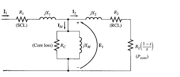
The final per-phase equivalent circuit is as shown below:
4. Power and Torque in Induction Motor
|
Losses and Power-Flow diagram
An induction motor can be basically described as a rotating transformer. Its input is a 3 phase system of voltages and currents. For an ordinary transformer, the output is electric power from the secondary windings. The secondary windings in an induction motor (the rotor) are shorted out, so no electrical output exists from normal induction motors. Instead, the output is mechanical. The relationship between the input electric power and the output mechanical power of this motor is shown below:
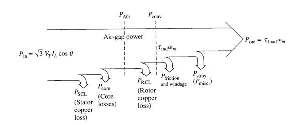
The input power to an induction motor Pin is in the form of 3-phase electric voltages and currents. The first losses encountered in the machine are I2R losses in the stator windings (the stator copper loss PSCL). Then, some amount of power is lost as hysteresis and eddy currents in the stator (Pcore). The power remaining at this point is transferred to the rotor of the machine across the air gap between the stator and rotor. This power is called the air gap power PAG of the machine. After the power is transferred to the rotor, some of it is lost as I2R losses (the rotor copper loss PRCL), and the rest is converted from electrical to mechanical form (Pconv). Finally, friction and windage losses PF&W and stray losses Pmisc are subtracted. The remaining power is the output of the motor Pout.
The core losses do not always appear in the power-flow diagram at the point shown in the figure above. Because of the nature of the core losses, where they are accounted for in the machine is somewhat arbitrary. The core losses of an induction motor come partially from the stator circuit and partially from the rotor circuit. Since an induction motor normally operates at a speed near synchronous speed, the relative motion of the magnetic fields over the rotor surface is quite slow, and the rotor core losses are very tiny compared to the stator core losses. Since the largest fraction of the core losses comes from the stator circuit, all the core losses are lumped together at that point on the diagram. These losses are represented in the induction motor equivalent circuit by the resistor RC (or the conductance GC). If core losses are just given by a number (X watts) instead of as a circuit element, they are often lumped together with the mechanical losses and subtracted at the point on the diagram where the mechanical losses are located.
The higher the speed of an induction motor, the higher the friction, windage, and stray losses. On the other hand, the higher the speed of the motor (up to nsync), the lower its core losses. Therefore, these three categories of losses are sometimes lumped together and called rotational losses. The total rotational losses of a motor are often considered to be constant with changing speed, since the component losses change in opposite directions with a change in speed.
Example 7.2
A 480V, 60Hz, 50hp, 3 phase induction motor is drawing 60A at 0.85 PF lagging. The stator copper losses are 2kW, and the rotor copper losses are 700W. The friction and windage losses are 600W, the core losses are 1800W, and the stray losses are negligible. Find:
a) The air gap power PAG
b) The power converted Pconv
c) The output power Pout
d) The efficiency of the motor
Power and Torque in an Induction Motor
By examining the per-phase equivalent circuit, the power and torque equations governing the operation of the motor can be derived.

The input current to a phase of the motor is:
Where

Thus, the stator copper losses, the core losses, and the rotor copper losses can be found.
The stator copper losses in the 3 phases are: PSCL = 3 I12 R1
The core losses : PCore = 3 E12 GC
So, the air gap power: PAG = Pin - PSCL - Pcore
 Also, the
only element in the equivalent circuit where the air-gap power can be consumed
is in the resistor R2/s. Thus, the air-gap power:
Also, the
only element in the equivalent circuit where the air-gap power can be consumed
is in the resistor R2/s. Thus, the air-gap power:
The actual resistive losses in the rotor circuit are given by:
PRCL = 3 IR2 RR
Since power is unchanged when referred across an ideal transformer, the rotor copper losses can also be expressed as:
PRCL = 3 I22 R2
After stator copper losses, core losses and rotor copper losses are subtracted from the input power to the motor, the remaining power is converted from electrical to mechanical form. The power converted, which is called developed mechanical power is given as:
![]()

And the rotor copper losses are noticed to be equal to the air gap power times the slip PRCL = s PAG
Hence, the lower the slip of the motor, the lower the rotor losses. Also, if the rotor is not turning, the slip is s=1 and the air gap power is entirely consumed in the rotor. This is logical, since if the rotor is not turning, the output power Pout ( = τload ωm) must be zero. Since Pconv = PAG - PRCL , this also gives another relationship between the air-gap power and the power converted from electrical and mechanical form:
Pconv = PAG - PRCL
= PAG - sPAG
Pconv = (1-s) PAG
Finally, if the friction and windage losses and the stray losses are known, the output power:
Pout = Pconv - PF&W - Pmisc
 The induced
torque in a machine was defined as the torque generated by the internal
electric to mechanical power conversion. This torque differs from the torque actually available at the terminals
of the motor by an amount equal to the friction and windage torques in the
machine. Hence, the developed torque is:
The induced
torque in a machine was defined as the torque generated by the internal
electric to mechanical power conversion. This torque differs from the torque actually available at the terminals
of the motor by an amount equal to the friction and windage torques in the
machine. Hence, the developed torque is:
 Other ways
to express torque:
Other ways
to express torque:
Separating the Rotor Copper Losses and the Power Converted in an Induction Motor's Equivalent Circuit
A portion of power transferred via the air gap will be consumed by the rotor copper loss and also converted into mechanical power. Hence it may be useful to separate the rotor copper loss element since rotor resistance are both used for calculating rotor copper loss and also the output power.
Since Air Gap power would require R2/s and rotor copper loss require R2 element. The difference between the air gap power and the rotor copper loss would give the converted power, hence;

Therefore the equivalent circuit would be modified to be as follows:
Example 7.3
A 460V, 25hp, 60Hz, 4 pole, Y-connected induction motor has the following impedances in ohms per phase referred to the stator circuit:
R1 = 0.641 Ω R2 = 0.332 Ω
X1 = 1.106 Ω X2 = 0.464 Ω Xm = 26.3 Ω
The total rotational losses are 1100W and are assumed to be constant. The core loss is lumped in with the rotational losses. For a rotor slip of 2.2% at the rated voltage and rated frequency, find the motor's
a) speed
b) stator current
c) power factor
d) Pconv and Pout
e) τind and τload
f) efficiency
5. Induction Motor Torque-Speed Characteristics
The torque-speed relationship will be examined first from the physical viewpoint of the motor's magnetic filed behaviour and then, a general equation for torque as a function of slip will be derived from the induction motor equivalent circuit.
Induced Torque from a Physical Standpoint
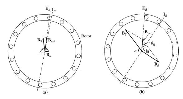
The magnetic
fields in an induction motor under light
loads The magnetic
fields in an induction motor under heavy
loads
No-load Condition
Assume that the induction rotor is already rotating at no load conditions, hence its rotating speed is near to synchronous speed. The net magnetic field Bnet is produced by the magnetization current IM . The magnitude of IM and Bnet is directly proportional to voltage E1 . If E1 is constant, then Bnet is constant. In an actual machine, E1 varies as the load changes due to the stator impedances R1 and X1 which cause varying volt drops with varying loads. However, the volt drop at R1 and X1 is so small, that E1 is assumed to remain constant throughout.
At no-load, the rotor slip is very small, and so the relative motion between rotor and magnetic field is very small, and the rotor frequency is also very small. Since the relative motion is small, the voltage ER induced in the bars of the rotor is very small, and the resulting current flow IR is also very small. Since the rotor frequency is small, the reactance of the rotor is nearly zero, and the max rotor current IR is almost in phase with the rotor voltage ER . The rotor current produces a small magnetic field BR at an angle slightly greater than 90 degrees behind Bnet. The stator current must be quite large even at no-load since it must supply most of Bnet .
The induced torque which is keeping the rotor running, is given by:
![]()
and its magnitude is ![]()
In terms of magnitude, the induced torque will be small due to small rotor magnetic field.
On-load Conditions
As the motor's load increases, its slip increases, and the rotor speed falls. Since the rotor speed is slower, there is now more relative motion between rotor and stator magnetic fields. Greater relative motion means a stronger rotor voltage ER which in turn produces a larger rotor current IR . With large rotor current, the rotor magnetic field BR also increases. However, the angle between rotor current and BR changes as well.
Since the rotor slip is larger, the rotor frequency rises (fr =sfe) and the rotor reactance increases (ωLR). Therefore, the rotor current now lags further behind the rotor voltage, and the rotor magnetic field shifts with the current. The rotor current now has increased compared to no-load and the angle δ has increased. The increase in BR tends to increase the torque, while the increase in angle δ tends to decrease the torque (τind is proportional to sin δ, and δ>90s). Since the first effect is larger than the second one, the overall induced torque increases to supply the motor's increased load.
As the load on the shaft is increased, the sin δ term decreases more than the BR term increases (the value is going towards the 0 cross over point for a sine wave). At that point, a further increase in load decreases τind and the motor stops. This effect is known as pullout torque
Modelling the torque-speed characteristics of an induction motor
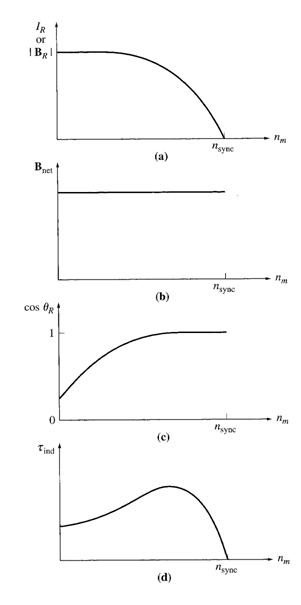
Looking at the induction motor characteristics, a summary on the behaviour of torque:
Note: ![]()
a) Rotor magnetic field will increase as the rotor current will increase (provided that the rotor core is not saturated). Current flow will increase as slip increase (reduction in velocity)
b) The net magnetic field density will remain constant since it is proportional to E1 (refer to equivalent induction motor equivalent circuit). Since E1 is assumed to be constant, hence Bnet will assume to be constant.
c) The angle will increase as slip increases. Hence the sin value will reduce until as such that the reduction of sin d will be greater than the increase of BR (pullout torque). Since is greater than 90 degrees, as such that:
![]()
where:
r is the angle between ER and IR (note that ER is in phase with Bnet since it is in phase with Bnet).
Adding the characteristics of all there elements would give the torque speed characteristics of an induction motor.
cos R can also be known as the motor power factor where:
The torque speed curve may be divided into 3 regions of operations:
a) Linear region or low slip region
b) Moderate slip region located until the pullout torque level.
c) High slip region
Typical values of pullout torque would be at about 200% to 250% of the rated full load torque of the induction machine. The starting torque would be about 150% than the rated full load torque; hence induction motor may be started at full load.
Graphical
development of an induction motor torque-speed characteristics
The Derivation of the Induction Motor Induced-Torque Equation
Previously we looked into the creation of the induced torque graph, now we would like to derive the Torque speed equation based upon the power flow diagram of an induction motor. We know that,
Comparing between the 2 equations, the second equation may be more useful since it is referenced to synchronous speed. Hence there is a need to derive PAG. By definition, air gap power is the power transferred from the stator to the rotor via the air gap in the induction machine. Based upon the induction motor equivalent circuit, the air gap power may be defined as:
Our next task is to find I2 (current flow in the rotor circuit). The easiest way is via the construction of the Thevenin equivalent circuit.
Thevenin's theorem states that any linear circuit that can be separated by two terminals from the rest of the system can be replaced by a single voltage source in series with an equivalent impedance.
Calculation via thevenin equivalent method
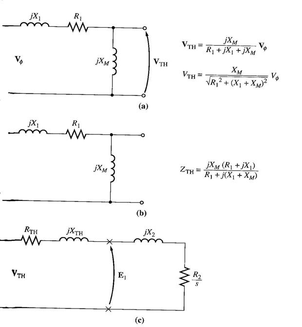
Derive the thevenin voltage (potential divider rule):

Hence the magnitude of thevenin voltage:
Since Xm >> X1 , Xm >> R1, therefore the magnitude may be approximated to:
Find the thevenin impedance
Take out the source and replace it with a short circuit, and derive the equivalent impedances.
Since Xm >> X1, Xm >> R1,
Representing the stator circuit by the thevenin equivalent, and adding back the rotor circuit, we can derive I2,
Hence the magnitude will be,
Hence air gap power,

Hence, induced torque,
If a graph of Torque and speed were plotted based upon changes in slip, we would get a similar graph as we had derived earlier.
Comments on the Induction Motor Torque Speed Curve
a) Induced Torque is zero at synchronous speed.
b) The graph is nearly linear between no load and full load (at near synchronous speeds).
c) Max torque is known as pull out torque or breakdown torque
d) Starting torque is very large.
e) Torque for a given slip value would change to the square of the applied voltage.
f) If the rotor were driven faster than synchronous speed, the motor would then become a generator.
g) If we reverse the direction of the stator magnetic field, it would act as a braking action to the rotor - plugging.
Since Pconv may be derived as follows:
![]()
Hence we may plot a similar characteristic to show the amount of power converted throughout the variation of load.
Maximum (Pullout) Torque in an Induction Motor
Since induced torque is equal to PAG / ωsync , the maximum pullout torque may be found by finding the maximum air gap power. And maximum air gap power is during which the power consumed by the R2/s resistor is the highest.
Based upon the maximum power transfer theorem, maximum power transfer will be achieved when the magnitude of source impedance matches the load impedance. Since the source impedance is as follows:
![]()
Hence maximum power transfer occurs during:
![]()
Hence max power transfer is possible when slip is as follows:

Put in the value of Smax into the torque equation,

From here we can say:
a) Torque is related to the square of the applied voltage
b) Torque is also inversely proportional to the machine impedances
c) Slip during maximum torque is dependent upon rotor resistance
d) Torque is also independent to rotor resistance as shown in the maximum torque equation.
By adding more resistance to the machine impedances, we can vary:
a) Starting torque
b) Max pull out speed
Example 7.4
A 2 pole, 50 Hz induction motor supplies 15kW to a load at a speed of 2950 r/min.
(a) What is the motor's slip?
(b) What is the induced torque in the motor in Nm under these conditions?
(c) What will the operating speed of the motor be if its torque is doubled?
(d) How much power will be supplied by the motor when the torque is doubled?
Example 7.5
A 460V, 25hp, 60Hz, 4-pole, Y-connected wound rotor induction motor has the following impedances in ohms per-phase referred to the stator circuit:
R1 = 0.641 Ω R2 = 0.332 Ω
X1 = 1.106 Ω X2 = 0.464 Ω Xm = 26.3 Ω
(a) What is the max torque of this motor? At what speed and slip does it occur?
(b) What is the starting torque?
(c) When the rotor resistance is doubled, what is the speed at which the max torque now occurs? What is the new starting torque?
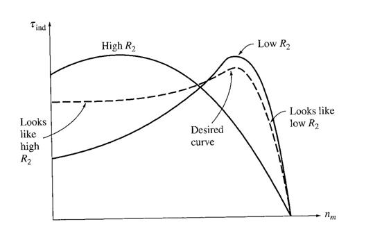
Variations in Induction Motor Torque-Speed Characterictics
A
torque-speed characteristic curve combining high-resistance effects at low speeds
(high slip) with low resistance effects at high speed (low slip).
Control of Motor Characteristics by Cage Rotor Design
Leakage reactance X2 represents the referred form of the rotor's leakage reactance (reactance due to the rotor's flux lines that do not couple with the stator windings.)
Generally, the farther away the rotor bar is from the stator, the greater its X2, since a smaller percentage of the bar's flux will reach the stator. Thus, if the bars of a cage rotor are placed near the surface of the rotor, they will have small leakage flux and X2 will be small.
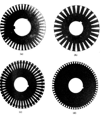
Laminations
from typical cage induction motor, cross section of the rotor bars (a) NEMA class A - large bars near the
surface (b) NEMA class B - large, deep rotor bars (c) NEMA class C - double-cage rotor design (d) NEMA class D - small bars near the
surface
NEMA (National Electrical Manufacturers Association) class A
Rotor bars are quite large and are placed near the surface of the rotor.
Low resistance (due to its large cross section) and a low leakage reactance X2 (due to the bar's location near the stator)
Because of the low resistance, the pullout torque will be quite near synchronous speed
Motor will be quite efficient, since little air gap power is lost in the rotor resistance.
However, since R2 is small, starting torque will be small, and starting current will be high.
This design is the standard motor design.
Typical applications - driving fans, pumps, and other machine tools.
NEMA class D
Rotor with small bars placed near the surface of the rotor (higher-resistance material)
High resistance (due to its small cross section) and a low leakage reactance X2 (due to the bar's location near the stator)
Like a wound-rotor induction motor with extra resistance inserted into the rotor.
Because of the large resistance, the pullout torque occurs at high slip, and starting torque will be quite high, and low starting current.
Typical applications - extremely high-inertia type loads.
Typical
torque-speed curves for different rotor designs.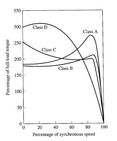
Deep-Bar and Double-Cage rotor design
How can a variable rotor resistance be produced to combine the high starting torque and low starting current of Class D, with the low normal operating slip and high efficiency of class A??
Use deep rotor bars (Class B) or double-cage rotors (Class C)
The basic concept is illustrated below:
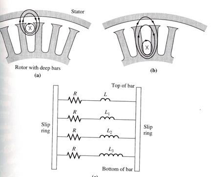
(a) For a current flowing in the top of the
bar, the flux is tightly linked to the stator, and leakage L is small. (b) At the bottom of the bar, the flux is
loosely linked to the stator, and leakage L is large. (c) Resulting equivalent circuit
NEMA Class B
At the upper part of a deep rotor bar, the current flowing is tightly coupled to the stator, and hence the leakage inductance is small in this region. Deeper in the bar, the leakage inductance is higher.
At low slips, the rotor's frequency is very small, and the reactances of all the parallel paths are small compared to their resistances. The impedances of all parts of the bar are approx equal, so current flows through all the parts of the bar equally. The resulting large cross sectional area makes the rotor resistance quite small, resulting in good efficiency at low slips.
At high slips (starting conditions), the reactances are large compared to the resistances in the rotor bars, so all the current is forced to flow in the low-reactance part of the bar near the stator. Since the effective cross section is lower, the rotor resistance is higher. Thus, the starting torque is relatively higher and the starting current is relatively lower than in a class A design.
Applications similar to class A, and this type B have largely replaced type A.
NEMA Class C
It consists of a large, low resistance set of bars buried deeply in the rotor and a small, high-resistance set of bars set at the rotor surface. It is similar to the deep-bar rotor, except that the difference between low-slip and high-slip operation is even more exaggerated.
At starting conditions, only the small bars are effective, and the rotor resistance is high. Hence, high starting torque. However, at normal operating speeds, both bars are effective, and the resistance is almost as low as in a deep-bar rotor.
Used in high starting torque loads such as loaded pumps, compressors, and conveyors.
NEMA Class E and F
Class E and Class F are already discontinued. They are low starting torque machines.
Starting Induction Motors
An induction motor has the ability to start directly, however direct starting of an induction motor is not advised due to high starting currents, which will be explained later.
In order to know the starting current, we should be able to calculate the starting power required by the induction motor. The Code Letter designated to each induction motor, which can be seen in figure 7-34, may represent this. (The starting code may be obtained from the motor nameplate).
![]()

Based upon example7-7, it is seen that to start an induction motor, there is a need for high starting current. For a wound rotor type induction motor, this problem may be solved by incorporating resistor banks at the rotor terminal during starting (to reduce current flow) and as the rotor picks up speed, the resistor banks are taken out.
For a squirrel cage rotor, reducing starting current may be achieved by varying the starting voltage across the stator terminal. Reducing the starting terminal voltage will also reduce the rated starting power hence reducing starting current. One way to achieve this is by using a step down transformer during the starting sequence and stepping up the transformer ratio as the machine spins faster (refer figure below).
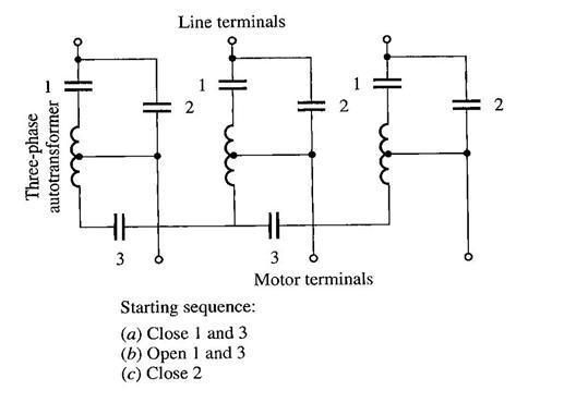
Induction motor starting circuits
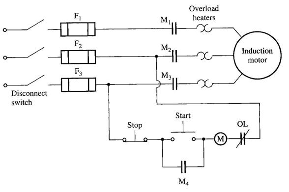
Operation:
When the start button is pressed, the relay or contactor coil M is energized, causing the normally open contacts M1, M2 and M3 to shut.
Then, power is applied to the induction motor, and the motor starts.
Contact M4 also shuts which shorts out the starting switch, allowing the operator to release it without removing power from the M relay.
When the stop button is pressed, the M relay is deenergized, and the M contacts open, stopping the motor.
A magnetic motor starter of this sort has several built in protective features:
a) Short Circuit protection - provided by the fuses
b) Overload protection - provided by the Overload heaters and the overload contacts (OL)
c) Undervoltage protection - deenergising of the M relays.
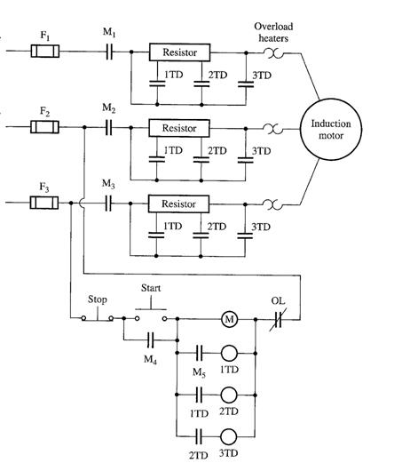 3 Step
resistive Starter Induction motor
3 Step
resistive Starter Induction motor
Operation:
Similar to the previous one, except that there are additional components present to control removal of the starting resistor. Relays 1TD, 2TD and 3TD are called time-delay relays.
When the start button is pushed, the M relay energizes and power is applied to the motor.
Since the 1TD, 2TD and 3TD contacts are all open, the full starting resistor are in series with the motor, reducing the starting current.
When M contacts close, the 1TD relay is energized. There is a finite delay before the 1TD contacts close. During that time, the motor speeds up, and the starting current drops.
After that, 1TD close, cutting out part of the starting resistance and simultaneously energizing 2TD relay. And finally 3TD contacts close, and the entire starting resistor is out of the circuit.
Speed Control of Induction Motor
Induction motors are not good machines for applications requiring considerable speed control. The normal operating range of a typical induction motor is confined to less than 5% slip, and the speed variation is more or less proportional to the load.
Since PRCL = sPAG , if slip is made higher, rotor copper losses will be high as well.
There are basically 2 general methods to control induction motor's speed:
a) Varying stator and rotor magnetic field speed
b) Varying slip
Varying the magnetic field speed may be achieved by varying the electrical frequency or by changing the number of poles.
Varying slip may be achieved by varying rotor resistance or varying the terminal voltage.
Induction Motor Speed Control by Pole Changing
There are 2 approaches possible:
a) Method of Consequent Poles (Old Method)
b) Multiple Stator Windings Method
Method of Consequent Poles
General Idea:
Consider one phase winding in a stator. By changing the current flow in one portion of the stator windings as such that it is similar to the current flow in the opposite portion of the stator will automatically generate an extra pair of poles.
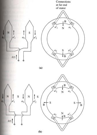
(a) In the 2-pole configuration, one coil
is a north pole and the other a south pole. (b) When the connection on one of the 2
coils is reversed, they are both north poles, and the south poles are called
consequent poles, and the windings is now a four -pole windings.
By applying this method, the number of poles may be maintained (no changes), doubled or halfed, hence would vary its operating speed.
In terms of torque, the maximum torque magnitude would generally be maintained.
Disadvantage:
This method will enable speed changes in terms of 2:1 ratio steps, hence to obtained variations in speed, multiple stator windings has to be applied. Multiple stator windings have extra sets of windings that may be switched in or out to obtain the required number of poles. Unfortunately this would an expensive alternative.
Speed Control by Changing the Line Frequency
Changing the electrical frequency will change the synchronous speed of the machine.
Changing the electrical frequency would also require an adjustment to the terminal voltage in order to maintain the same amount of flux level in the machine core. If not the machine will experience:
a) Core saturation (non linearity effects)
b) Excessive magnetization current.
Varying frequency with or without adjustment to the terminal voltage may give 2 different effects:
a) Vary frequency, stator voltage adjusted - generally vary speed and maintain operating torque.
b) Vary Frequency, stator voltage maintained - able to achieve higher speeds but a reduction of torque as speed is increased.
There may also be instances where both characteristics are needed in the motor operation; hence it may be combined to give both effects.
With the arrival of solid-state devices/power electronics, line frequency change is easy to achieved and it is more versatile to a variety of machines and application.
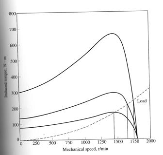
Speed Control by Changing the Line Voltage
Varying the terminal voltage will vary the operating speed but with also a variation of operating torque. In terms of the range of speed variations, it is not significant hence this method is only suitable for small motors only.
Speed Control by Changing the Rotor Resistance
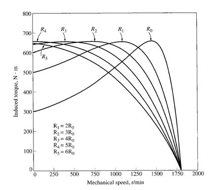 It is only
possible for wound rotor applications but with a cost of reduced motor
efficiency.
It is only
possible for wound rotor applications but with a cost of reduced motor
efficiency.
Determining Circuit Model Parameters
There are basically 3 types of tests that can be done on an Induction motor:
a) No-load test
b) DC test
c) Locked Rotor test or Blocked Rotor test
These tests are performed to determine the equivalent circuit elements - R1, R2, X1, X2 and XM.
The No-Load Test
The no-load test measures the rotational losses and provides info about its magnetization current.
The induction motor is not loaded; hence any load will be based upon frictional and mechanical losses. The rotor will be rotating at near synchronous speed hence slip is very small. The no load test circuit and induction motor equivalent circuit is shown below:
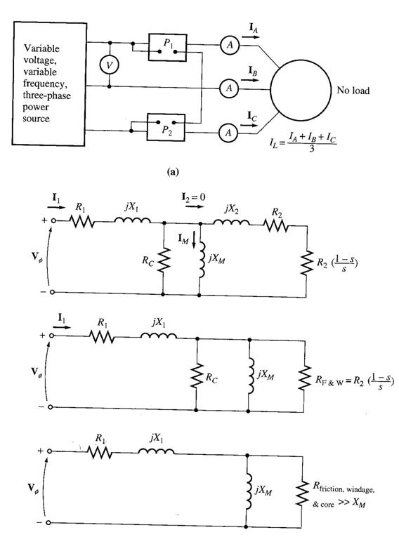
With its very small slip, the resistance corresponding to its power converted, R2(1-s)/s, is much larger than the resistance corresponding to the rotor copper losses R2 and much larger than the rotor reactance X2.
In this case, the equivalent circuit reduces to the last circuit. There, the output resistor is in parallel with the magnetization reactance XM and the core losses RC.
In this motor at no-load conditions, the input power measured by the meters must equal the losses in the motor. The rotor copper losses are negligible because I2 is extremely small (because of the large load resistance R2(1-s)/s), so they may be neglected. The stator copper loss is given by:
![]()
Hence,
Prot = Pcore + PF&W + Pmisc
Also,
The DC Test
This is a test for R1 independent of R2, X1, and X2.
DC voltage is applied to the terminals of the stator windings of the induction motor. Since it is DC supply, f = 0, hence no induced current in the rotor circuit. Current will flow through the stator circuit. Reactance is zero at dc. Thus, the only quantity limiting current flow in the motor is the stator resistance, and it can be determined.
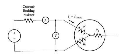 Assume we
have a Y connected induction motor circuit as shown:
Assume we
have a Y connected induction motor circuit as shown:
Steps:
a) DC voltage is applied across the motor terminal and current flow is adjusted to rated condition (to simulate normal operating condition)
b) Voltage and current flow is noted.
Based upon the test configuration,
Since we are able to determine the value of R1, hence PSCL can be calculated. Unfortunately, this method is not accurate since it is done using a DC power source where skin effects, that occurs when an ac voltage is applied to the windings, are neglected.
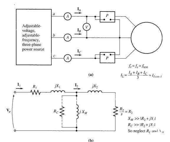 The Locked-Rotor Test
Steps:
a) The rotor is locked.
b) AC voltage is applied across the stator terminals and current flow is adjusted to full load condition.
c) Measure voltage, current and power flow.
Since the rotor is locked, hence slip would be at a maximum as such that the R2 terms are small. Hence bulk of the current will flow through the rotor circuit rather than the magnetizing branch. Therefore the overall circuit is reduced to:

From here we may calculate:

Also,
Note: This test is generally inaccurate due to the fact that in real operation, slip would vary from starting and as the rotor approaches operating speeds. Since slip would also correlate to rotor current and voltage frequency (at small slip, frequency is small, at high slip, frequency is high). Frequency would affect the rotor reactance. Therefore, this test is done with a lower supply frequency (25% or less) to simulate small slip during operation. However, the true value of X may be found in the following formulae:
Since R1 may be found from the DC test, therefore we can calculate R2. The value of XLR may also be calculated by using the formulae below:

Example 7-8
The following test data were taken on a 7.5 hp, 4-pole, 208V, 60Hz, desing A, Y-connected induction motor having a rated current of 28A.
DC Test VDC = 13.6 V IDC = 28.0 A
No-load test
VT = 208 V f = 60 Hz
IA = 8.12 A Pin = 420W
IB = 8.20 A
IC = 8.18 A
Locked-rotor test:
VT = 25 V f = 15 Hz
IA = 28.1 A Pin = 920W
IB = 28.0 A
IC = 27.6 A
(a) Sketch the per-phase equivalent circuit for this motor
(b) Find the slip at the pullout torque, and find the value of the pullout torque.
| Contact |- ia legatura cu noi -| | |
| Adauga document |- pune-ti documente online -| | |
| Termeni & conditii de utilizare |- politica de cookies si de confidentialitate -| | |
| Copyright © |- 2024 - Toate drepturile rezervate -| |
|
|
|||
|
|||
|
|||
Referate pe aceeasi tema | |||
|
| |||
|
|||
|
|
|||