|


 |  |

| Afaceri | Agricultura | Comunicare | Constructii | Contabilitate | Contracte |
| Economie | Finante | Management | Marketing | Transporturi |
Instalatii
|
|
Qdidactic » bani & cariera » constructii » instalatii AFB - ghid de instalare a automatizatii sau cutii de comanda |
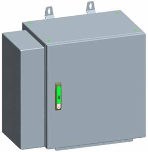
AFB - ghid de instalare a automatizatii sau cutii de comanda
Overview
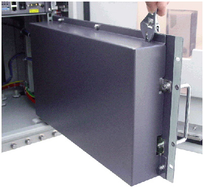
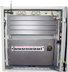
Physical appearance of AFB
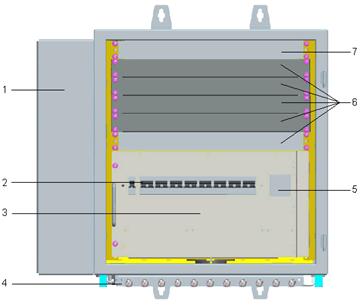
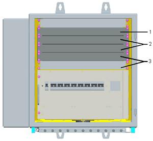
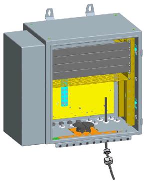
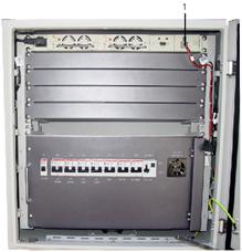
Internal structure
|
(1) Heat exchanger |
(2) MCB |
(3) Power distribution unit |
|
(4) External grounding bar |
(5) Maintenance socket |
(6) User devices |
|
(7) AC/DC rectifier |
|
|
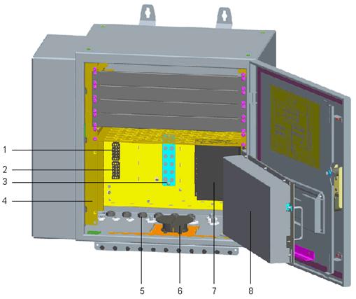
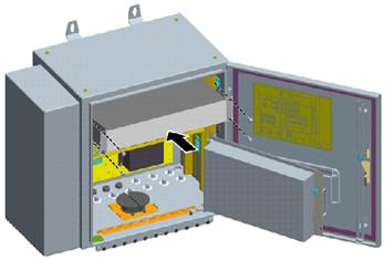
Devices installed in the AFB before delivery
|
(1) AC input wiring terminal (for heat exchanger) |
(2) DC input wiring terminal (for heat exchanger) |
(3) Internal grounding bar |
|
(4) Mounting bar |
(5) Cable hole |
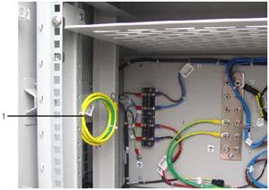
(6) Fiber coiler |
|
(7) Surge protection module |
(8) Cover of the power distribution unit |
|
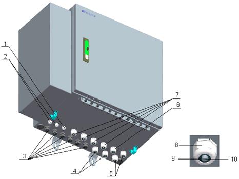
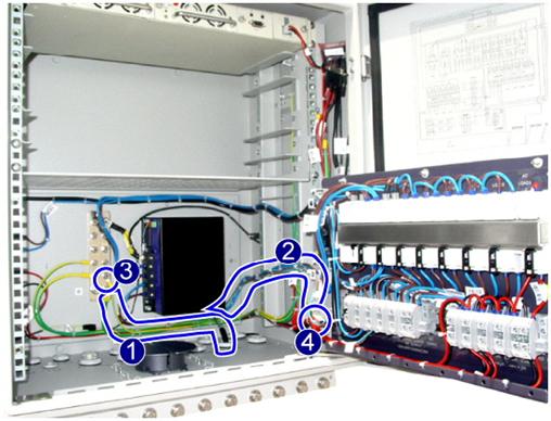
Cable holes
|
(1) GPS |
(2) Tran 2, Tran 3 |
(3) F.O.0 to F.O.5 |
|
(4) Tran 0, Tran 1 |
(5) SPARE 0, SPARE 1 |
(6) AC IN |
|
(7) AC LOAD 0 to AC LOAD 3 |
(8) Nut |
(9) Waterproof filler |
|
(10) Waterproof stick |
|
|
Installation instruction for AFB
Application Scenarios of AFB
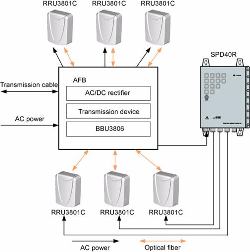
Installation instructions
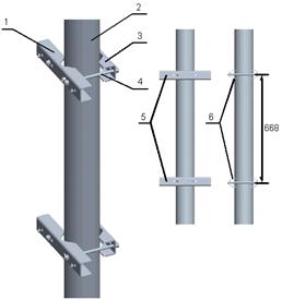
Installing the AFB Case on metal pole
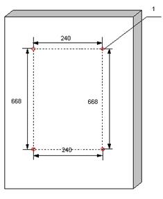
Installing the AFB Case on the wall
Installing the AC/DC Rectifier
Installing the Transmission Device
Installing AFB Cables
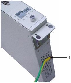
Installing the PGND cable
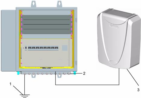
|
(1) Grounding bar at your site |
(2) External grounding bar of the AFB |
(3) Device connected to the AFB |
Installing the AC Input Power
Cable of the AFB Removing the
cover
Leading the cable in
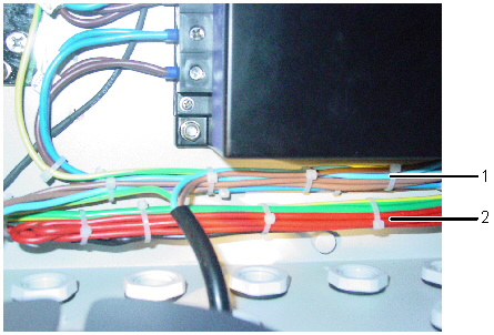
Routing the AC and DC power cables separately
|
(1) AC power cable |
(2) DC power cable |
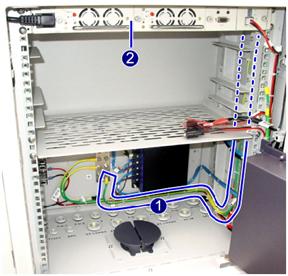
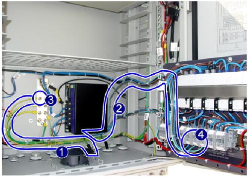
Connecting and routing the cables
|
(1) PE wire (green and yellow) |
(2) L wire (brown) and N wire (blue) |
|
(3) Grounding terminal of the PE wire |
(4) AC wiring terminal (for input |
Installing the AC Output Power Cable of the AFB
Connections of the AC output power
cable
|
(1) PE wire (green and yellow) |
(2) L wire (brown) and N wire (blue) |
|
(3) Grounding terminal of the PE wire |
(4) AC wiring terminal (for output) |
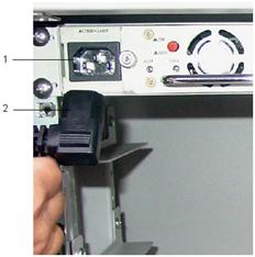
Installing the AC Input Power Cable to the AC/DC Rectifier
Just connect the AC connector to AC power socket on the AC/DC rectifier
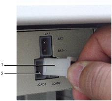
Installing the DC Output Power Cable to the AC/DC Rectifier
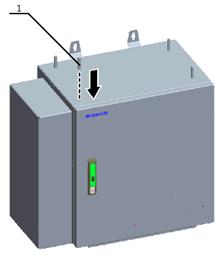
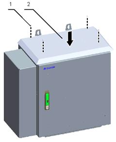
Installing the Sun Shield of the AFB
Checklists for BBU3806 Hardware Installation
|
SN |
Check Items |
|
|
The redundant part of the power cable or PGND cable is stripped off rather than coiled. |
|
|
The lugs at both ends of the power cable or PGND cable are securely soldered or crimped. |
|
|
The bare wires and lugs at the wiring terminals are tightly wrapped up with insulating tapes or heat-shrinkable tubes. |
|
|
The flat washers and spring washers are well mounted to all wiring terminals. |
|
|
The power cable and PGND cable are routed separately from other cables. |
|
|
Both ends of each cable are legible. That is, both ends of the cable are labeled. |
|
|
|
| Contact |- ia legatura cu noi -| | |
| Adauga document |- pune-ti documente online -| | |
| Termeni & conditii de utilizare |- politica de cookies si de confidentialitate -| | |
| Copyright © |- 2025 - Toate drepturile rezervate -| |