|


 |  |
| Aeronautica | Comunicatii | Drept | Informatica | Nutritie | Sociologie |
| Tehnica mecanica |
Tehnica mecanica
|
|
Qdidactic » stiinta & tehnica » tehnica mecanica Huawai Installation instruction for BTS3803C |
Huawai Installation instruction for BTS3803C
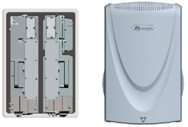
Overview
Physical
structure of BTS3803C
Configuration principles
|
Configuration |
Rack |
Positions of the Modules |
|
One BBU |
|
|
|
One BBU |
|
|
|
|
|
|
|
One BBU |
|
|
|
|
|
|
Installation instruction for BTS3803C
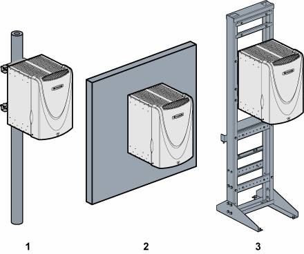
Scenarios of RRU3801C installation
|
(1) Installing the BTS |
(2) Installing the BTS |
(3) Installing the BTS |
Installation instructions
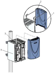
Installing the BTS3803C rack
Installing the BTS3803C rack on the Metal Pole
1) Mounting
the fixture assemblies (unit: mm)
|
(1) M10 x 180 bolt |
(2) Spring washer 10 |
(3) Flat washer 10
|
(4) Pole fixture |
Installing
the Installing the rack
|
(1) Tab |
(2) Anchor slot |
Securing Securing the rack
|
(1) Metal Pole |
(2) Rack |
(3) Insulating washer |
|
(4) Flat washer 10 |
(5) Spring washer 10 |
(6) M10 x 45 bolt |
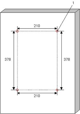
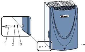
Installing the BTS3803C rack on the wall.
Determining the anchor points (unit: mm)
Installing the expansion bolt assembly
|
(1) M10 x 75 bolt |
(2) Filling tube |
(3) Spring washer 10 |
(4) Flat washer 10 |
|
(5) Expansion tube |
(6) Nut |
(7) Guiding rib |
(8) Guiding slot |
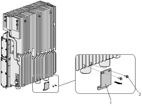
Removing the attachment plate
from the back of the rack
|
(1) Attachment plate |
(2) M4 x 14 screw |
Securing the mounting bracket
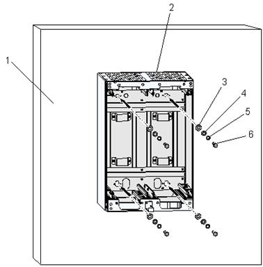
|
(1) Wall |
(2) Rack |
(3) Insulating washer |
|
(4) Flat washer 10 |
(5) Spring washer 10 |
(6) M10 x 75 bolt |
Installing
the BTS3803C Module
Installing the RRU3801C (40W)
Removing one plastic strip
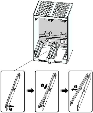
Removing other plastic strips and U-shaped spacers
Removing the
locking piece of the 40 W RRU3801C module
Installing the
40 W RRU3801C
module in the rack
Securing the
RRU3801C module - 1
Securing the
RRU3801C module - 2
Installing the BBU3806C
module Installing BBU3806C is the same as RRU3801C module
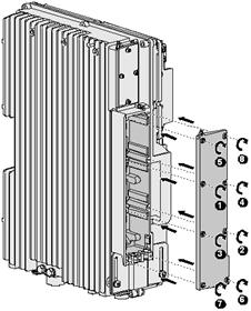
Removing the Cover Plate from the BBU3806C Cabling Cavity
Turning the flap at 90° outwards
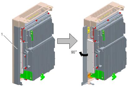
Removing the cover plate
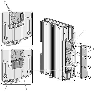
Removing the Cover Plate from the RRU3801C Cabling Cavity (40 W)
1) Removing
the cover plate
Installing BTS3803C Cables
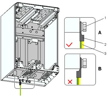
Installing PGND cables
Connecting
the PGND cable to the BTS3803C
Installing
the power cables of BBU3806C /RRU3801C
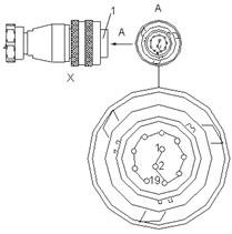
Connect the round and waterproof connector to the socket labeled PWR at the module bottom, and then tighten the connector clockwise until you hear a click sound indicating that the connector is installed in place.
Connect the other end of the power cable.
Waterproof both ends of the protection tube.
Label the power cable.
Installing the E1/T1/J1
Cable of the BBU3806C
Connect the 32-pin, round and waterproof connector to the port labeled 8*E1/T1/J1 at the module bottom, and then tighten the connector clockwise until you hear a click sound indicating that the connector is installed in place
Connect the other end of the E1/T1/J1 cable according to the cable type.
Label the cable.
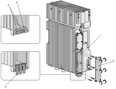
Installing the BBU3806C -RRU3801C CPRI fiber cables
Inserting the ESFP optical
module into the ESFP socket
Connect the two LC connectors labeled
Remove the waterproof fillers from the cable troughs of the cabling cavity. Route the CPRI optical cable along cable troughs 1, 2, and 3 numbered from left to right. Then bind the CPRI optical cable and the binding slot on the lower angle piece using cable ties.
Route the optical cable close to the RRU
Connect the two LC connectors labeled
Label the CPRI optical cable
Installing the Dry Contact
Alarm Cable of the BBU3806C
Connect the DB15 female connector to the connector labeled RS485&EXT_ALM at the module bottom
Connect cold-pressed terminals at the other end to the external alarm device
Label the dry contact alarm cable
Installing the cover plate
for BBU3806C /RRU3801C
Installing the housing
cover for BTS3803C .
Checklists for BTS3803C Hardware Installation
Refer to hardware installation checklist
of RRU
| Contact |- ia legatura cu noi -| | |
| Adauga document |- pune-ti documente online -| | |
| Termeni & conditii de utilizare |- politica de cookies si de confidentialitate -| | |
| Copyright © |- 2025 - Toate drepturile rezervate -| |
|
|
|||
|
|||
|
|||
Analize pe aceeasi tema | |||
|
| |||
|
|||
|
|
|||